Check out the topics covered under Class 12 Physics Moving Charges and Magnetism in this article.
One of the most important concepts in electricity, mobile charge, and magnetism, has been studied for over a century. The relationship between moving charge and magnetism was a phenomenon observed when pointing a needle.
We know that the orientation of the needle remains tangent to an imaginary circle centered on a straight wire, and the plane of the circle is perpendicular to the wire. However, the orientation of the needle changes when the current flows. This has led to the theory that charge flow leads to the creation of magnetic fields. This article contains concepts explained in Mobile charge and magnetism.
Ampere’s Swimming Rule
Using Ampere's law of swimming, if a swimmer were to imagine swimming along a conductor facing the needle and in the direction of the electric current, the north pole of the needle would be deflected to the left. It states that an electric current creates a magnetic field and provides a way to calculate it.
Magnetic Field
A stationary charge creates an electric field around it, and a moving charge creates an electric field around it, exerting a force on the moving charge. This electric field is called the magnetic field and is a vector quantity denoted by 'B'. The nature of the magnetic field surrounding a conductor is highly dependent on the geometry of the conductor.
Motion of a Charged Particle in a Magnetic Field
When a charged particle ‘q’ is thrown in a magnetic field B with a velocity of v, the force acting on the particle is given by the equation
F = qvB.sinθ
where θ = the angle between the velocity and the magnetic field.
Since the magnetic force on a charged particle is perpendicular to its velocity, it does not work on it and as a result, has no effect on the particle’s kinetic energy or speed.
Case 1: θ = 0° or 180°
The path followed is a straight line
As the angle between v and B is 0° or 180°, a charged particle that is thrown parallel or antiparallel to a magnetic field will not experience any magnetic force and will continue to travel in a straight line at a constant speed.
Case 2: θ = 90°
The path followed is circular
The path of a charged particle is circular when projected perpendicular to a uniform magnetic field. Here, the magnetic Lorentz force works as a centripetal force, causing the charged particle to move at a constant speed in a circular path of radius R.
F = qvB = mv2/R
⇒ R = mv/qB
Angular velocity (ω) = v/R = qB/m
Time period of revolution, T = 2π/ω = 2πm/qB
Frequency of revolution = 1/T = qB/2πm
Biot-Savart Law
The Biot-Savart law, named after Jean-Baptiste Biot and Felix Savart, is an equation that gives the magnetic field produced by an energized segment used as a vector quantity known as the current element.
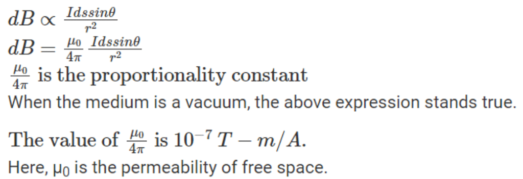
It states that the magnetic field due to a small current element at any instant is directly proportional to the sine of the angle between the length of the current element, the current, the direction of the current and the line connecting the points to the current element. , which is also inversely proportional to the square of the distance to this point.
Now let's think about the small element 'ds' of the conductor. The magnetic field 'dB' produced by this element should be measured at a position 'P' a distance 'r' away from the element. Let 'r' be the position vector and 'θ' the angle between them. The 'ds' direction and the current direction are the same.
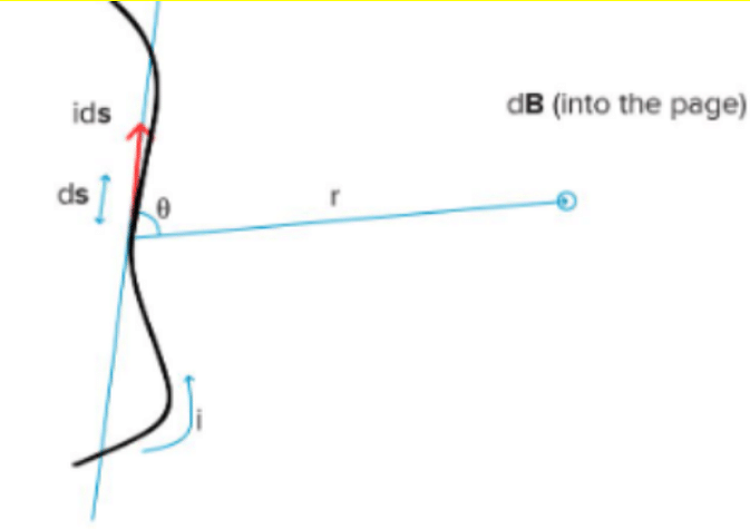
According to the Biot-Savart law, the magnitude of the magnetic field ``dB'' is directly proportional to the current ``I'' and the element length ``ds'', and inversely proportional to the square of the distance ``r''. The direction of the magnetic field is perpendicular to the direction of the plane containing ds and r.
Ampere’s Circuital Law
According to Ampere's circuit equation, the line integral of the stationary magnetic field across the closed loop is equal to μ0 times the total current (Ie) flowing through the surface bounded by the loop.
![]()
Ampere’s Circuital Law Application
Magnetic Field Due to Straight Infinite Current-Carrying Wire
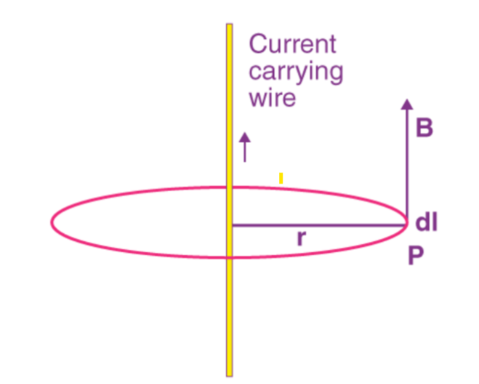
Consider a live wire that is infinitely straight. Create an ampere loop with a wire on the axis with a circle of radius 'r'. Since the magnetic field is tangential at all points of the loop, the magnitude of the magnetic field is similar at all points.
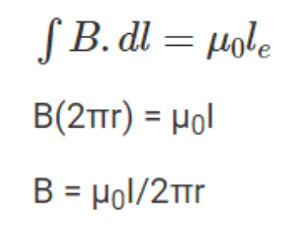
Apply Ampere's Law
Magnetic Field due to a Solenoid
A solenoid is a cylindrical coil made up of several turns of wire. The wires are coated with an insulating material so that they are electrically isolated when the turns touch.
In general, the solenoid length is greater than the cross-sectional radius of the solenoid. If the turns of the solenoid are closely spaced, each turn can be considered a circular coil and the net magnetic field at any point is the vector sum of the magnetic fields due to all the turns.
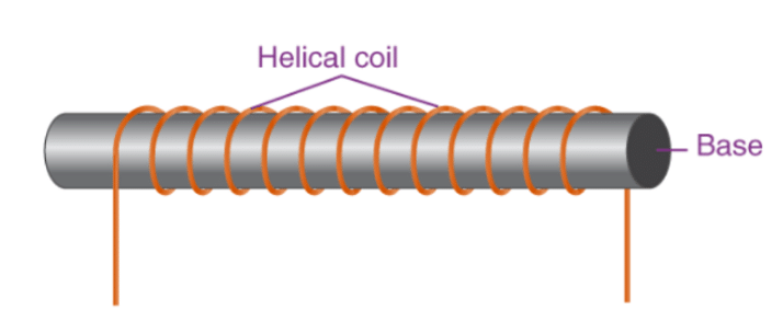
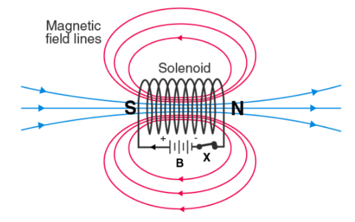
An electromagnet is treated as an ideal electromagnet if the windings are tightly wound and the length is much larger than the radius. In such a solenoid the field outside is weaker than inside the solenoid. Furthermore, the internal magnetic field is uniform over a considerable volume and along the axis of the solenoid. The figure below shows a cross-section of a long solenoid with 'n' turns.
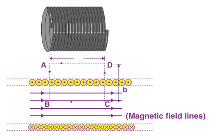
The field can be evaluated using Ampere's cyclic law. Consider a rectangular loop ABCD where the direction of integration is counterclockwise. For this loop

If a solenoid has ‘n’ rounds of wire in a unit length, then the current is given by I = nai
Therefore, μ0(nai) = B x a
⇒ B = μ0(nai)/a
B = μ0(ni)
Magnetic Force
It has been observed that a static charge exerts almost no force. On the other hand, if a velocity 'v' is given in the direction of the current, the charge 'q' will be deflected towards the wire. From this we can conclude that the moving charged particles are exposed to the magnetic field. The Lorentz force is the result of the interaction of electric and magnetic forces on a point charge.
Suppose a point charge 'q' is moving with velocity 'v' and is placed in the position vector 'r' at a given time 't'. If there is an electric field 'E' and a magnetic field 'B' at this location, the force on the charge 'q' will be equal.

Magnetic Force on a Current-Carrying Conductor
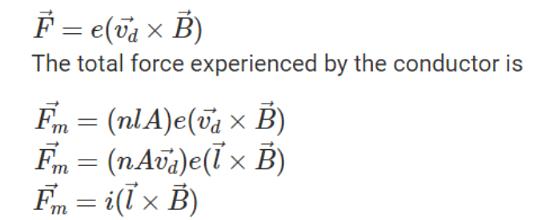
Suppose a current-carrying conductor is placed in a uniform magnetic field, and let l and A be the length and cross-sectional area of the conductor, respectively. Free electrons in the wire have a drift velocity of 'vd', which is opposite to the direction of current flow. The force experienced by each electron is
Force Between Two Parallel Current-Carrying Wires
Currents i1 and i2 are carried in the same direction by two parallel wires. Each conductor creates a magnetic field at the position of the other conductor. The other conductor reacts to this magnetic field. Currents flowing in the same direction in conductors attract each other.
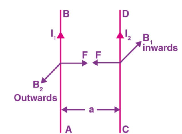
Let us assume that the conductors are infinitely long and calculate the force per unit length between them.
Let B1 be the magnetic fields due to the first conductors.

Moving Coil Galvanometer
A galvanometer consists of a coil with multiple turns that are free to rotate about a fixed axis within a uniform radial magnetic field. The coils are wound around a cylindrical soft iron core that keeps the magnetic field radial at all coil positions.
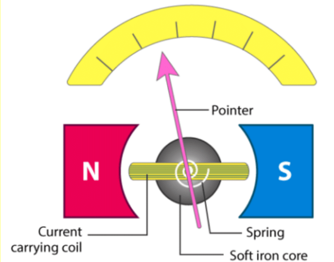
When current flows through the coil, a torque acts on it which is force multiplied by the perpendicular distance between the forces.
τ = F x b
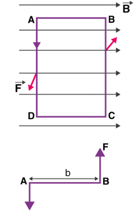
The torque acting on the coil’s single loop - ABCD
τ = Bilb (Where l x b is the area of the coil ‘A’)
Hence, the torque acting on ‘n’ turns of the coil is given by
τ = niAB
The coil rotates due to the magnetic torque, and the phosphor bronze strip twists. The spring ‘S’ linked to the coil provides a counter torque or restoring torque kθ, which results in a constant angular deflection.
Under equilibrium conditions, kθ = niAB
where k = the spring’s torsional constant (restoring torque per unit twist). A pointer linked to the spring ‘S’ shows the deflection on the scale.
θ = (nAB/k)i
The quantity nAB / k is a constant for a given galvanometer.
Galvanometer as Ammeter
A galvanometer is a highly sensitive instrument that can only be used as an ammeter to measure current in a circuit.
A galvanometer provides a full-scale current on the order of μA. Due to the large resistance, the current value in the circuit changes.
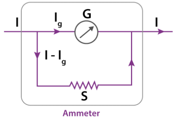
As a solution to these challenges, a small resistance ‘rs’, known as shunt resistance, is connected in parallel with the galvanometer coil, allowing the shunt to carry the majority of the current.
Vgalvanometer = Vshunt
IgRg = (I – Ig)S
S = (I – Ig)/Ig
Ig = [S/(S + Rg)]I
Ig ∝ I
The deflection in the galvanometer is proportional to the current passing through it.
θ = (1/G)Ig
θ ∝ Ig
Therefore, θ ∝ I
The galvanometer is connected in parallel with the shunt resistance. As a result, the effective resistance, which is the resistance of an ammeter, may be calculated as
Reff = RGS/(RG + S)
Galvanometer as Voltmeter
A galvanometer can be used to determine the potential difference between two sections of the circuit, but it must be connected across the circuit. It also consumes very little power. Otherwise, the voltage measurement will greatly destroy the original structure. Generally, interference from measuring devices is minimized to 1%. To ensure this, place a large resistor 'R' in series with the galvanometer.
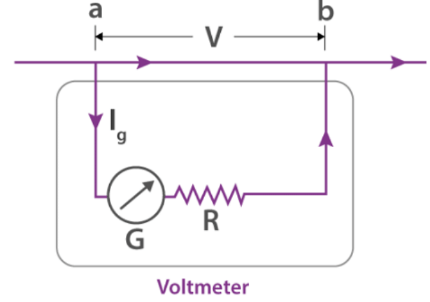
G = resistance of the galvanometer
R = resistance connected in series
Let ‘V’ volt be the potential difference that the voltmeter will detect, and Ig is the current. Hence, the voltage between a and b is given by the equation
V = IgR + IgG
= Ig (R + G)
⇒ R = (V/Ig) - G
This is the resistance that must be connected in series with the galvanometer to convert it into a voltmeter ranging of 0-V volts.


