This article will introduce you to Ohm's Law and its applicability to electronics. You'll learn about the history of Ohm's law, how it works, and some practical examples.
Table of Contents
Ohm's law was developed in 1826 by Georg Simon Ohm. It claims that, under constant temperature and other physical conditions, the amount of electric current flowing through a conductor is directly proportional to the voltage and inversely proportional to its resistance.
Ohm’s Law Detailed Description and Formula
According to the law of electricity, the direct current's intensity is directly related to the potential difference and inversely proportional to the circuit’s resistance. Thus, Ohm’s law establishes the relationship between voltage (V) and current (I) across two ends of a conductor where resistance (R) provided by the conductor to allow the flow of current is constant.
The mathematical relationship is described with the following formula:
V = I*R
We can use the formula in two more variations:
I = V/R
R = V/I
- In electrical circuits, the value of resistors required for the proper functioning of the circuit is derived by using Ohm's law.
- Most of the branches use electrical use Ohm's law. It is inapplicable to semiconductors (non-ohmic conductors).
- Further, Ohm's law applies to finding the current flow in a circuit where we can easily measure the voltage (V) across a known resistor.
- Ohm's law applies when the temperature and other physical variables are constant. The temperature can sometimes rise as the current increases.
Example:
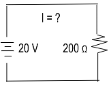
In an electrical circuit, the resistance of 200 Ohms and the voltage supply is 20 Volts. Find the current of the electric circuit.
Solution:
V = 20, R = 200 Ω
I = V / R = 20V / 200Ω
=> 0.2A = 200mA
Ohm’s Law Units
Here are Ohm’s law units that are used to derive the results:

Ohm’s Law - Vector Form
Material science and electromagnetics are the fields where you will see the usage of Ohm's law in vector form. Ohm's Law is shown as, in vector form,
→ →
J = σ E
Where,
→
J is the current density which is the vector equivalent of the current.
→
E is an electric field, the vector equivalent of potential difference, and σ is conductivity, which is the reciprocal of resistivity.
J = E, where it stands for electrical conductivity, E for the electric field, and J for the current density, is the microscopic form of Ohm's law.
Ohm’s Law and its Applications
There are various uses and applications of Ohm's law. Following are some examples of how Ohm's Law is used:
- Ohm's law maintains the desired voltage drop across the electrical components.
- The value of a circuit's voltage, resistance, or current can be determined using Ohm's law, which estimates power usage.
- In DC ammeters and other DC shunts, the current is diverted using Ohm's Law.
Experimental Verification of Ohm's Law
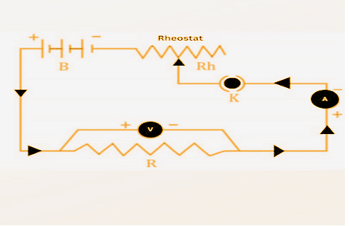
The experiment below demonstrates Ohm's law. The step-by-step procedure is mentioned in the points below:
- At first, the key (K) is closed, and the rheostat is adjusted to get the ammeter (A) and voltmeter (V) minimum reading.
- Gradually the current in the circuit is increased by moving the sliding terminal of the rheostat.
- While the process is ongoing, the current flowing in the circuit and the corresponding value of potential difference across the resistance wire R are recorded.
- This way, different sets of values of voltage and current are obtained.
- For each set of values of V and I, the ratio of V/I is calculated.
- When you calculate the ratio V/I for each case, you will notice that it is almost the same. So V/I = R, which is a constant.
Relation Between Voltage, Current, and Resistance
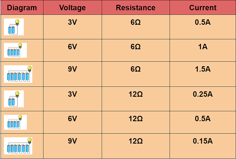
The chart below depicts the relationship between voltage, current, and resistance. Suppose we are tripling and doubling the voltage. In that case, that results in doubling and tripling the circuit's current, i.e., if the voltage is 3V and the current is 6Ω, the current will be 0.5A.
Likewise, suppose we double the overall resistance. In that case, it breaks down the circuit's current into half, i.e., 3V, and the current is 12Ω. The current will be 0.25A.
Further, the relationship between voltage and current is V ∝ I.
Water Pipe Analogy of Ohm’s Law
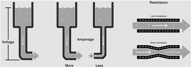
When various voltages are applied to the ends of each resistance, Ohm's Law defines the current flow through each resistance. The water-pipe analogy of Ohm's law helps us understand electrical circuits because we cannot see electrons.
- The water flowing through pipes is a mechanical system analogous to an electrical circuit.
- The voltage applied is analogous to water pressure; the current can be taken as the amount of water flowing through the pipe, and the resistance can be understood as the size of the pipe.
- When greater pressure or voltage is applied, a greater amount of water or current will flow through the pipe. The bigger the pipe, the lower the resistance.
Ohm’s Law Magic Triangle
Ohm's law magic triangle is employed to derive results and remember various equations. In case the resistance is asked, voltage and current values are present. We can easily calculate the resistance by applying the formula R=V/I.
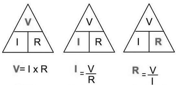
Below are examples of how Ohm's law magic triangle is used to determine the voltage.
Question: What is the amount of current that an electric bulb pulls from a 200V source if the resistance of the bulb filament is 800Ω?
Solution:
We are given V = 200V and R = 800Ω.
Now, we have the current,
⇒I = V.R
⇒I = 200V/ 800Ω
⇒I = 0.025 A
Question:
An EMF source of 6.0 V is connected to a purely resistive electrical appliance (a light bulb). An electric current of 3.0 A flows through it. Consider the conducting wires to be resistance-free. Calculate the resistance offered by the electrical appliance.
Solution:
When we are asked to determine the value of resistance when voltage and current values are given, we cover R in the triangle. This leaves us with only V and I, more precisely V/ I.
Substituting the values in the equation, we get
⇒R = V/ I
⇒R = 6 V/ 3 A = 2 Ω
⇒R = 2 Ω
Calculation of Electrical Power Using Ohm’s Law
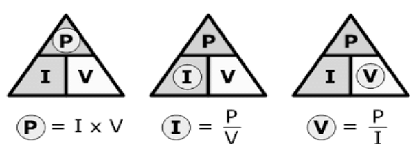
We can use Ohm's law to derive the value of electrical power measured in watts. Further, the rate at which the electrical energy is converted into other forms of energy, such as heat or mechanical energy, is called eclectic power. The following formulas do the representation of the same:
- P = V*I when the values for voltage and current are given.
- P = V²/R when the values for voltage and resistance are given.
- P = I²*R when the values for current and resistance are given.
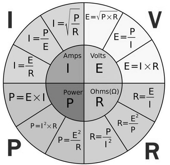
Ohm’s Law Pie Chart
The following diagram shows all the equations used to identify the voltage, current, resistance, and power. Also, it helps in understanding the relationship between various parameters.
- V=I*R, V=P/I, V=√P*R
- I=V/R, I=P/V, I=√P/R
- R=V/I, R=V²/P, R=P/I²
- P=V*I, P = I²*R, P=V²/R
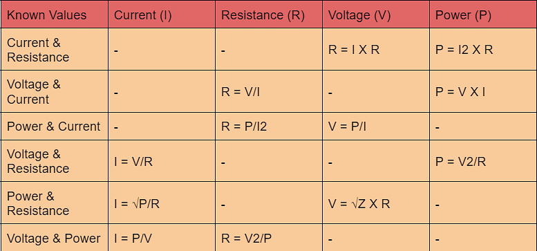
Ohm’s Law Matrix Table
Here is Ohm's law matrix table to understand the values of each equation. The table will help in enhancing your practice.
Ohm’s Law Limitations
Some limitations are involved while practically using Ohm's law to derive the results of some equations. Some of them are as follows:
- The law is not applied to unilateral electrical elements like diodes and transistors as they permit the current to flow in a particular direction.
- In the case of non-linear electrical elements with parameters like capacitance, resistance, and others, the ratio between voltage and current won't be constant. It is because time makes it difficult to use Ohm's law.
With the help of Ohm's law, we have established the relationship between electric current and potential difference in an electric circuit. Further, we can identify the connection between voltage, current, and resistance through Ohm's law pie chart, matrix, or magic triangle.







POST YOUR COMMENT